Search
Communications

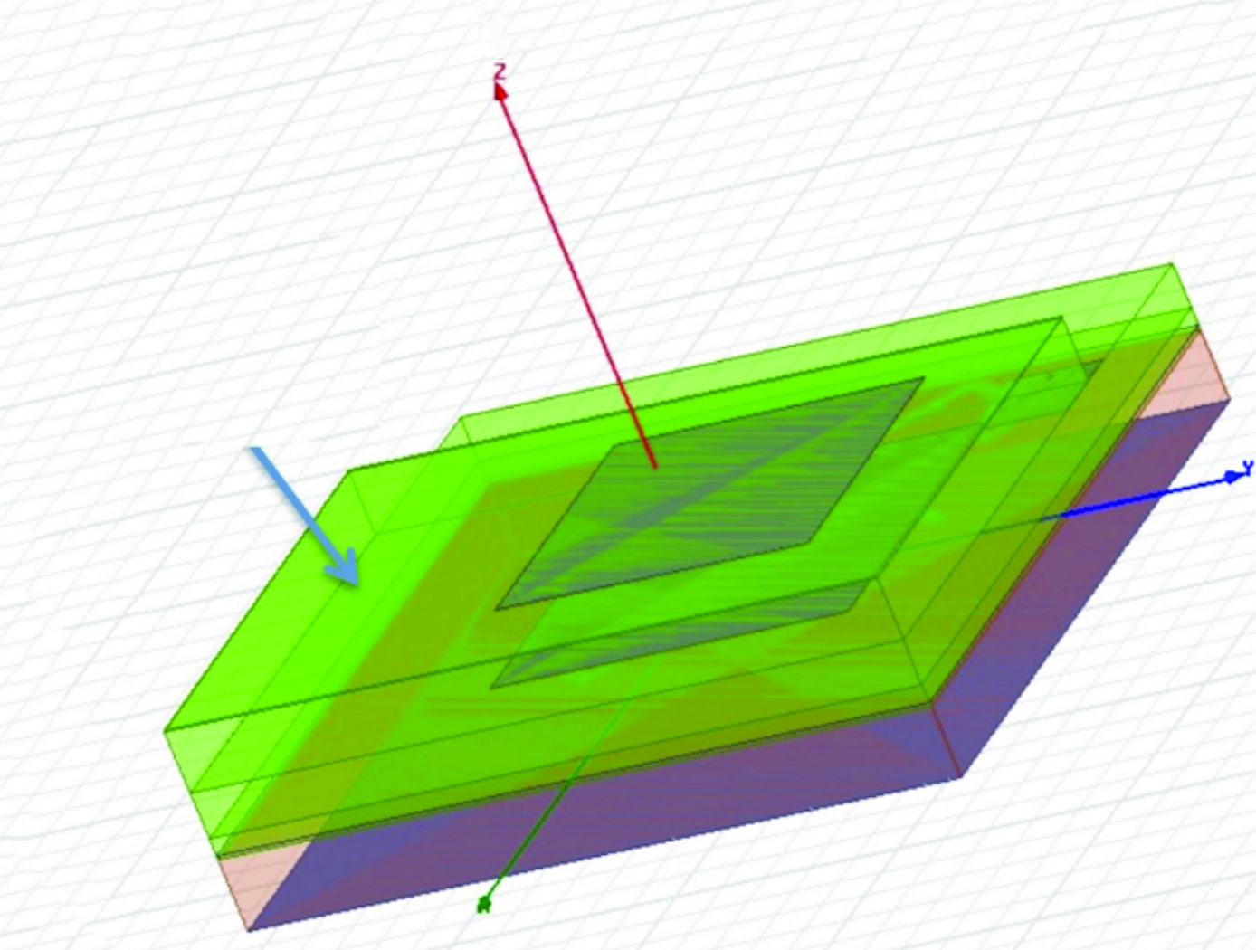
High Performance, All-Metal X-Band Patch Antenna
The patch antenna consists of two radiating metal patch elements, a metal feed circuit, choke rings, several alignment spacers, a SMA connector, and a mounting lid giving the antenna a total diameter of 54 mm; small enough to fit in a coffee cup. The signal is carried between the lower patch and the circuit via a coaxial transmission structure, in which the probes are the inner conductor and the antenna structure is the outer conductor. The patch antenna is constructed entirely of metal, offering rugged physical durability while delivering superior performance. This advanced material not only enables the antenna to handle higher power loads (exceeding 10 watts) but also ensures exceptional stability under demanding conditions—outperforming standard patch antennas made with traditional dielectric materials. It is also not susceptible to the manufacturing variability incurred from using dielectrics. Ideally, this metallic design also allows for reentry and reuse across missions.
The patch antenna is designed with integrated choke rings to effectively mitigate multipath signal interference, delivering an impressive front-to-back ratio of over 35 dB. Its integrated polarizer circuit enhances signal clarity and boosts overall efficiency, ensuring reliable communication in challenging environments. With support for both right- and left-handed circular polarization, the antenna achieves a co-polarization peak gain of 9 dBi and an axial ratio of less than 3 dB within a wide 50-degree orientation range. These advanced features provide superior signal performance and consistent clarity across diverse applications.
Although designed for space and planetary exploration applications, the antenna may also be valuable for terrestrial use cases with rugged conditions. The X-band patch antenna is at technology readiness level (TRL) 5 (component and/or breadboard validation in relevant environment) and is available for patent licensing.
communications
Multi-and Wide-Band Single-Feed Patch Antenna
NASA's patch antenna technology exhibits higher operational bandwidth (on the order of 20%) than typical patch antennas (less than 10%) and can operate across integer-multiple frequency bands (e.g. S/X, C/X, S/C). Testing of the antenna design has demonstrated > 6dB of gain on both S and X bands (boresight), with an axial ratio of < 6dB and voltage standing wave ratio (VSWR) < 3:1 throughout the entire near-Earth network (NEN) operating bands (22.4GHz and 88.4GHz) with hemispherical coverage. The patch size is on the order of 10 x 10 cm and with associated electronics, is about 1 cm in height.
communications
Lightweight, Self-Deployable Helical Antenna
NASA's newly developed antenna is lightweight (at or below 2 grams), low volume (at or below 1.2 cm3), and low stowage thickness (approx. 0.7 mm), all while delivering high performance (at or above 10 dBi gain). The antenna includes a novel design-material combination in a helical coil conformation. The design allows the antenna to compress for stowage (e.g., satellite launch), then self-deploy at the desired time in orbit.
NASA's lightweight, self-deployable helical antenna can be integrated into a thin-film solar array (or other large deployable structures). Integrating antenna elements into deployable structures such as power generation arrays allows spacecraft designers to maximize the inherently limited resources (e.g., mass, volume, surface area) available in a small spacecraft. When used as a standalone (i.e., single antenna) setup, the the invention offers moderate advantages in terms of stowage thickness, volume, and mass. However, in applications that require antenna arrays, these advantages become multiplicative, resulting in the system offering the same or higher data rate performance while possessing a significantly reduced form factor.
Prototypes of NASA's self-deployable, helical antenna have been fabricated in S-band, X-band, and Ka-band, all of which exhibited high performance. The antenna may find application in SmallSat communications (in deep space and LEO), as well as cases where low mass and stowage volume are valued and high antenna gain is required.

